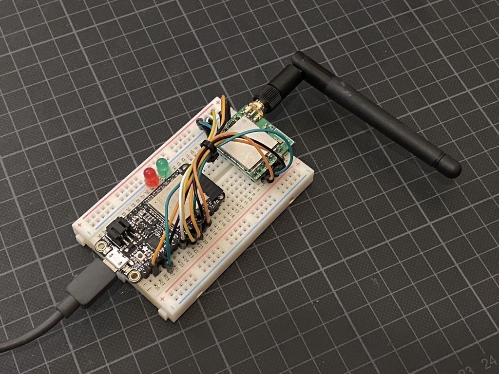
 A homemade RNode, based on an ESP32 board and a transceiver module, ready for use
This article will outline the general process, and provide the information you need, for building your own RNode from a few basic modules. The RNode will be functionally identical to a purchased device.
Once you have learned the put together a custom RNode with your own choice of components, you can use these skills to create your own RNode designs from scratch, using either a custom-designed PCB, or simply by mounting your choice of modules in a enclosure or case.
If you haven't already, you migh also want to check out how to install the RNode firmware directly on pre-made LoRa development boards.
A homemade RNode, based on an ESP32 board and a transceiver module, ready for use
Since there is not one right way to cut this pie, this article will probably not give the exact steps for the combination of components you choose, but will instead attempt to provide you with the information you need to build RNodes from a wide variety of microcontroller boards and LoRa modules. Generally speaking, you will need three things to construct a working RNode:
Currently, the RNode firmware supports a variety of different microcontrollers, and more are being added regurlarly. That means that there is a lot of boards to choose from. You can probably use most boards that are based on either the ATmega1284P, ATmega2560 or ESP32 microcontrollers. Regarding microcontroller boards there is a few key points to take note of:
Regarding the LoRa transceiver module, there is going to be an almost overwhelming amount of options to choose from. To narrow it down, here are the essential characteristics to look for:
Keeping those things in mind, you should be able to select a suitable combination of microcontroller board and transceiver module.
Ok, having gone through the endless combinations and selected a board and a module, you are actually almost done. Connecting the devices together is pretty simple, and should only take a few minutes. I recommend that you place both devices in a solderless breadboard initially, to make sure everything is working as expected. Once you have a working setup, you can make it more durable and permanent by soldering it to a prototyping board, and connecting permanent lines between the devices.
In the photo above I used an Adafruit Feather ESP32 board and a ModTronix inAir4 module. That will result in an RNode suitable for the 420 MHz to 520 MHz range. To complete the device I did the following:
The pin layouts of your transceiver module and microcontroller board will vary, but you can look up the correct pin assignments for your processor type and board layout in the Config.h file of the RNode Firmware.
Once the hardware is assembled, you are ready to load the firmware onto the board and configure the configuration parameters in the boards EEPROM. Luckily, this process is completely automated by the RNode Configuration Utility. To prepare for loading the firmware, make sure that python and pip is installed on your system, then install the rns package (which includes the rnodeconf program) by issuing the command:
pip install rns
If installation goes well, you can now move on to the next step.
Take Care: A LoRa transceiver module must be connected to the board for the firmware to start and accept commands. If the firmware does not verify that the correct transceiver is available on the SPI bus, execution is stopped, and the board will not accept commands. If you find the board unresponsive after installing the firmware, or EEPROM configuration fails, double-check your transceiver module wiring!
Having double-checked that everything is connected correctly, it is time to power up the board and install the firmware. Run the rnodeconf autoinstaller by executing the command:
rnodeconf --autoinstall
The installer will now ask you to insert the device you want to set up, scan for connected serial ports, and ask you a number of questions regarding the device. When it has the information it needs, it will install the correct firmware and configure the necessary parameters in the device EEPROM for it to function properly.
If the install goes well, you will be greated with a success message telling you that your device is now ready. To confirm everything is OK, you can query the device info with:
rnodeconf --info /dev/ttyUSB0
Remember to replace /dev/ttyUSB0 with the actual port the installer used in the previous step. You should now see rnodeconf connect to your device and show something like this:
[2022-01-27 20:11:22] Opening serial port /dev/ttyUSB0...
[2022-01-27 20:11:25] Device connected
[2022-01-27 20:11:25] Current firmware version: 1.26
[2022-01-27 20:11:25] Reading EEPROM...
[2022-01-27 20:11:25] EEPROM checksum correct
[2022-01-27 20:11:25] Device signature validated
[2022-01-27 20:11:25]
[2022-01-27 20:11:25] Device info:
[2022-01-27 20:11:25]   Product            : LilyGO LoRa32 v2.0 850 - 950 MHz (b0:b8:36)
[2022-01-27 20:11:25]   Device signature   : Validated - Local signature
[2022-01-27 20:11:25]   Firmware version   : 1.26
[2022-01-27 20:11:25]   Hardware revision  : 1
[2022-01-27 20:11:25]   Serial number      : 00:00:00:02
[2022-01-27 20:11:25]   Frequency range    : 850.0 MHz - 950.0 MHz
[2022-01-27 20:11:25]   Max TX power       : 17 dBm
[2022-01-27 20:11:25]   Manufactured       : 2022-01-27 20:10:32
[2022-01-27 20:11:25]   Device mode        : Normal (host-controlled)
On the hardware side, you should see the status LED flashing briefly approximately every 2 seconds. If all of the above checks out, congratulations! Your RNode is now ready to use.
If you want to use it with Reticulum, Nomad Network, LoRaMon, or other such applications, leave it in the default Normal (host-controlled) mode.
If you want to use it with legacy amateur radio applications that work with KISS TNCs, you should set it up in TNC mode.