This build recipe will help you create an RNode that is suitable for mobile and handheld operation, and offers both wireless and wired connectivity to host devices. It is also useful for permanent installation indoors, or even outdoors, as long as it is protected from water ingress and direct sunlight.
Depending on the board you use, it will offer a workable frequency range between 420 and 520 MHz, or 820 and 1020 MHz, and a maximum TX power of 17 dBm (50 mW).
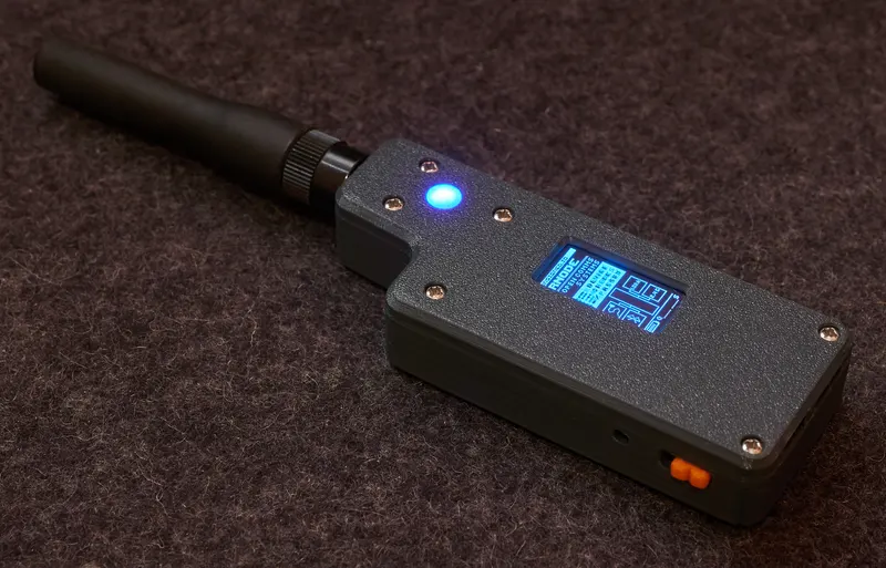
When you have completed this recipe, you will end up with a fully-featured RNode device, similar to the one pictured below. To make it as easy as possible to complete this guide, make sure to read it all in its entirity before starting. I also recommend you familiarise yourself with the required materials, and the software tools needed for the setup.
To complete this build recipe, you will need access to the following items:
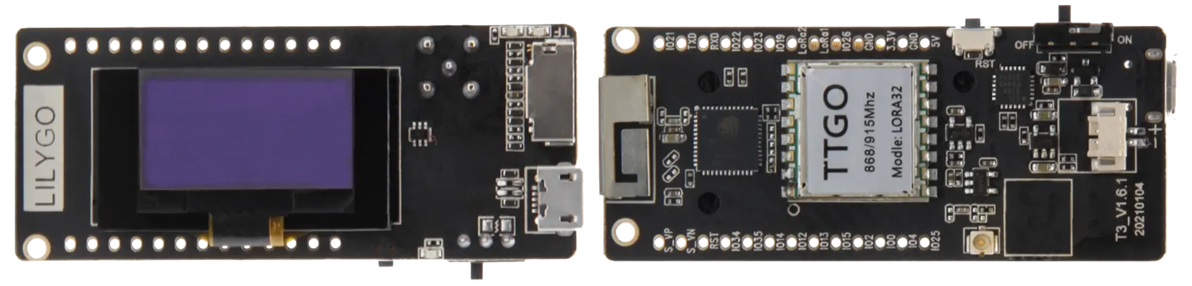
This RNode design is using a LilyGO LoRa32 v2.1 board, in either the 433 MHz, 868 MHz, 915 MHz or 923 MHz variants. It seems that the 868, 915 and 923 MHz variants are in fact completely identical, and all offer a frequency range between 820 and 1020 MHz. The 433MHz variants offer a frequency range between 420 and 520 MHz.
These boards are also sold under many different "brand" names other than LilyGO, but using the images below, you should be able to identify the correct ones.
It is easiest to obtain the version of the board with an u.FL (sometimes also labeled IPX or IPEX) antenna connector, instead of the SMA connector. This version comes with an SMA to u.FL pigtail, which is installed into the 3D-printed case. If it is not possible to obtain this version, you can use the one with an SMA connector, either as is, or by removing the SMA connector, and using the on-board u.FL connector instead.
If you do not wish to use the 3D-printable case included in this guide, it does not matter which version you get. There is no functional difference between the boards with SMA and u.FL connectors.
If you want to use the case provided for this build guide, and you have the version with an SMA connector, you will have to desolder the SMA connector, and activate the u.FL connector instead (it's already installed on all the boards, just not activated on the SMA connector versions).
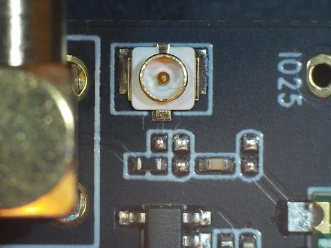
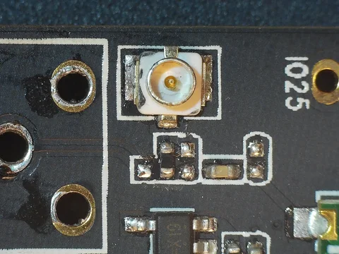
To activate the u.FL connector, you will just have to "rotate" the small resistor next to the antenna connectors by 90 degrees, so it "points" at the connector you wish to use.
Please note that the "resistor" is actually just a zero-ohm jumper. If you don't feel like fiddling around with small components, you can simply remove it, and bridge the relevant gap with a blob of solder.
Refer to the following two pictures to locate the resistor that needs moving:
You will also need to dismount the OLED display from the small acrylic riser on the board, and unscrew and discard the riser. Be careful not to damage the display or ribbon cable while doing this. The OLED display will be mounted directly into a matching slot in the 3D-printed case.
As before, if you do not want to use the 3D printed case supplied here, it's probably much easier to keep the display on the board, and you can simply skip this step.
In addition to the board, you will need a few other components to build this RNode.
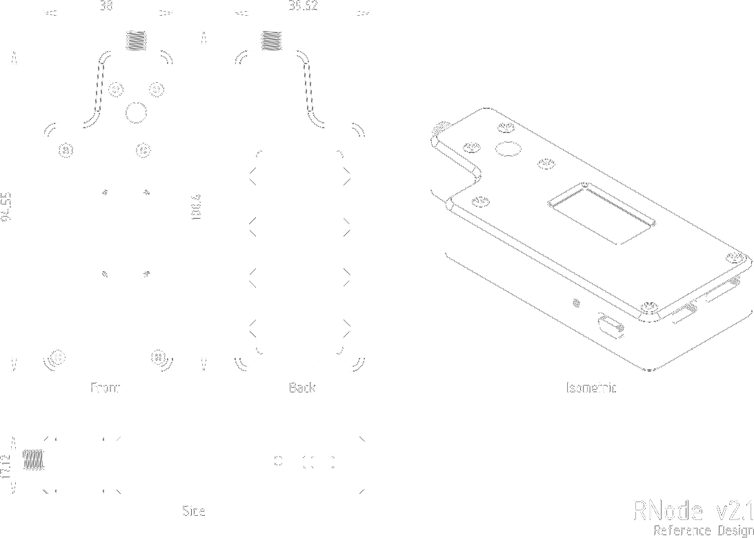
To complete the build of this RNode, you will need to 3D-print the parts for the casing. Download, extract and slice the STL files from the parts package in your preferred software.
LED_Window.stl file is a light-guide for the NeoPixel LED, mounted in the circular cutout at the top of the device.LED_Guide.stl file is a light-guide for the power and charging LEDs, mounted in the rectangular grove at the bottom of the device.Power_Switch.stl file is a small power-switch slider, mounted in the matching grove on the bottom-left of the device.Case_Top.stl file is the top shell of the case. It holds the OLED display and NeoPixel RGB LED, and mounts to the bottom shell of the case with 6 M2 screws. The screw holes in both the top and bottom shells of the case are dimensioned to be self-threading when screws are inserted for the first time. Do not over-tighten.Case_Bottom_Small_Battery.stl file is the default bottom shell of the case. It holds batteries up to approximately 700mAh.Case_Bottom_Large_Battery.stl file is an alternative bottom shell for the case. It holds batteries up to approximately 1100mAh.Case_Bottom_No_Battery.stl file is an alternative bottom shell for the case. It does not have space for a battery, but results in a very compact device.Case_Battery_Door.stl file is the door for the battery compartment of the device. It snap-fits tightly into place in the bottom shell, and features a small slot for opening with a flathead screwdriver or similar.All files are dimensioned to fit together perfectly without any scaling on a well-tuned 3D-printer.
The recommended layer height for all files is 0.15mm for FDM printers.
To install and configure the RNode Firmware on the device, you will need to install the rnodeconf program on your computer. This is included in the rns package, that can be installed using the pip package manager:
pip install rns
When the rnodeconf program is installed, you can continue to the next step.
Once the rnodeconf program is installed, we will use it to install the RNode Firmware on your device, and do the initial provisioning of configuration parameters. This process can be completed automatically, by using the auto-installer. Run the rnodeconf auto-installer with the following command:
rnodeconf --autoinstall
Please Note! If you are connected to the Internet while installing, the autoinstaller will automatically download any needed firmware files to a local cache before installing.
If you do not have an active Internet connection while installing, you can extract and use the firmware from this device instead. This will only work if you are building the same type of RNode as the device you are extracting from, as the firmware has to match the targeted board and hardware configuration.
If you need to extract the firmware from an existing RNode, run the following command:
rnodeconf --extract
If rnodeconf finds a working RNode, it will extract and save the firmware from the device for later use. You can then run the auto-installer with the --use-extracted option to use the locally extracted file:
rnodeconf --autoinstall --use-extracted
This also works for updating the firmware on existing RNodes, so you can extract a newer firmware from one RNode, and deploy it onto other RNodes using the same method. Just use the --update option instead of --autoinstall.
With the firmware installed and configured, and the case parts printed, it's time to put it all together.
Congratulations, Your Handheld RNode is now complete!
Flip the power switch, and start using it!